Data Communication and Networking
Learning Objectives:
·
Describe the communication system with its basic
elements and model.
·
Describe the data communication with its
elements and mode.
·
Define and apply LAN and WAN.
·
Describe transmission medium and use it.
·
Define terminologies for transmission
impairments.
·
Introduce network architecture.
·
Define basic terms and tools used in computer
network.
·
Define network tools, devices and topologies and
use them.
·
State the concept of OSI Reference Model and
Internet Protocol Addressing.
2.1 CONCEPT OF COMMUNICATION SYSTEM
COMMUNICATION SYSTEM
·
Communication is the process of sending or
receiving data or information between two or more devices.
·
The communication system is formed by the
elements involved for exchanging information.
·
In a communication system, the source (i.e.,
sender) generates the information or signals and they are transferred to the
destination (i.e., receiver) through communication channels or transmission media.
·
Radio broadcasting, television broadcasting,
telephone communication, mobile communication, computer network, etc. are some
examples of communication systems.
2.2 BASIC ELEMENTS OF COMMUNICATION SYSTEM
Transmitter, communication channel and receiver are the main
basic elements of communication system.
A transmitter receives an input i.e., message or information
signal and converts the message signal into electric signal or electromagnetic
wave, which is again superimposed on the carrier wave and is transferred to the
receiver through the communication channel. The receiver receives and separates
the electric signal from the carrier wave, and again it converts the electric
signal back to its original message signal. In this way, data or information is
transferred from one place to another.
Information/Message signal
·
It is the entity that is to be transmitted.
·
It can be in the form of text, audio, video,
pictures, pressure, temperature, etc.
·
It must be converted into electrical signals to
make it suitable for transmission through the communication channel.
·
When you talk on a telephone, your voice acts as
a message signal.
Electrical signal
·
It may be an analog signal or a digital signal.
·
Analog signal continuously changes its value
with time.
·
Digital signal is in the form of pulses.
Transmitter
•
It is an equipment that is used for signal
processing.
•
A transmitter contains a device called a
transducer that converts one form of energy or signal into another form of
energy or signal.
•
On the input side and output side, there are transducers.
•
The transducer presented at the input side of
the communication system is called an input transducer.
•
The input transducer receives the message signal
and converts the signal into the electric signal or electromagnetic signal for
transmission through a transmission channel.
•
Microphones and photodetectors are the common
input transducers. A microphone in telephone converts audio signals (sound
signals) into electrical signals. A photodetector converts light signals into
electrical signals.
Modulation & Demodulation
•
The electromagnetic signal cannot be transmitted
over a long distance as it becomes weaker when it transmits away from the
sender.
•
It is like how you cannot throw a piece of paper
far away. But when you tie the piece of paper with a stone (i.e., carrier), it
can be thrown far away.
•
A modulator in a transmitter superimposes the
original signal on the carrier wave (i.e. wave having a high frequency) to
transmit the signal over a long distance.
•
The process of superimposing of message signal
on a carrier wave is called modulation. The resultant wave is called the
modulated wave, which is to be transmitted. Modulation increases the strength
of a signal without changing the parameters of the original signal.
•
The process of retrieving the original signal
back from the modulated signal is known as demodulation.
Types of modulations
a. Amplitude modulation
b. Frequency modulation
c. Phase modulation
Amplitude modulation
·
The process of changing the amplitude of the
carrier wave in proportion to the amplitude of the message signal is called
amplitude modulation.
·
In this modulation, the frequency of the
amplitude modulated wave remains the same as that of the carrier wave.
Frequency Modulation (FM)
·
It is a technique or process in which the
frequency of the message signal is varied by modulating it with a carrier wave.
·
In this modulation, the carrier wave amplitude
remains same.
·
It is better than amplitude modulation because
it eliminates noise from various sources.
PHASE MODULATION (PM)
·
In this modulation, the phase of the carrier
wave changes in response to signal wave.
·
Phase modulated waves are immune to noise to a
greater extent.
Communication Channel/Medium
·
A communication channel or medium through which information
is transmitted from the transmitter to the receiver is known as a communication
channel.
·
The modulated signal is propagated through the communication
channel or medium.
·
A communication channel may be wire, cable, or
wireless (i.e., space).
RECEIVER
· A
receiver is an arrangement or device that extracts the message or information from
the transmitted signal at the output end of the channel and reproduces it in a
suitable form as the original message signal.
·
A TV set is an example of a receiver. In the
demodulator part of a receiver, the modulated signals are demodulated.
·
The process of separation of electric signals
from the carrier wave is known as demodulation. An output transducer in a
receiver converts the demodulated. signals, i.e. electric signals back to its
original form.
·
A speaker is an example of a transducer that
converts electrical signals into sound signals which are easily understandable
by humans at the destination.
Amplifier
•
The electronic circuit or device that increases
the amplitude or the strength of the transmitted signal is called an amplifier.
•
When the signal strength becomes less than the
required value, amplification can be done anywhere in between the transmitter and
the receiver.
•
A DC power source will provide for the
amplification.
Repeater
•
It is the device that receives the transmitted
signal, amplifies it and
•
sends it to the next repeater without distorting
the original signal.
•
Repeaters are placed at different locations in
between the transmitter and receiver.
ANTENNA
•
An antenna is basically a metallic object, often
a collection of wires.
•
It is a device that will radiate and receive
electromagnetic waves.
•
Antennas are used in both transmitters and
receivers. The electromagnetic waves are polarized according to the position of
the antenna.
2.3 BLOCK DIAGRAM OF COMMUNICATION SYSTEM /MODEL
The block diagram given below shows how message signal are
transferred from source to receiver.
•
The block diagram has mainly three parts:
transmitting, communication channel and receiving.
•
An input message generated by a source flow to
the input transducer.
•
The input signal/message is required to convert
into electrical signal or electromagnetic wave to transmit the message at a far
distance.
•
The input transducer converts one form or energy
into another. For example, your voice i.e., in sound energy is converted into
electrical signal by the input transducer.
•
The electrical signal flows to the modulator
which superimposes the electrical signal on the carrier wave.
•
The modulated wave is transmitted to the
receiver through the communication channel.
•
The communication channel which transmits the
modulated wave is not perfect.
•
The imperfection in the communication channel
decreases the strength of the signal and the signal is required to amplify or
boost by amplifier (such as a repeater).
•
And finally, modulated signal reaches at the
receiver.
•
The demodulator in the receiver separates the
electrical signal from the carrier wave. The demodulated signal flows to the
output transducer, which converts the electrical signal back to its original
signal.
•
For example, your voice is retrieved and
presented to another person at another location via a speaker.
2.5 COMMUNICATION MODE
•
Data transmission mode (i.e., communication
mode) defines the direction of the flow of data between two communication
devices connected on the network.
•
It is the flow of signals from one communication
device to another communication device on the network.
Types of communication modes
a. SIMPLEX
b. HALF DUPLEX
c. FULL DUPLEX
SIMPLEX
•
In the simplex communication mode, communication
(i.e., the transmission of data) can take place in only one direction i.e.,
unidirectional.
•
A simplex device can only send or receive data.
•
The transmission of data from a mainframe to a
monitor, data entered through a keyboard to a computer, audio sent to a
speaker, etc. are the examples of simplex communication mode.
•
The transmission of data through radios and
televisions is simplex.
•
A networking device hub is also a simplex
device.
HALF DUPLEX
•
It is two-way or bidirectional communication in
which data can transfer in both directions, but only in one direction at a
time.
•
A half-duplex device can alternately send and
receive data.
•
This is the most common type of transmission for
voice communications because only one person is supposed to speak at a time.
•
It is also used to connect a terminal to a
computer. The terminal might transmit data and then the computer responds with
an acknowledgement.
•
The transmission of data through a Walkie-Talkie
and from a station to another station are Half Duplex.
FULL- DUPLEX
•
In
full-duplex transmission mode, both sender and receiver can send and receive
data simultaneously.
•
A full-duplex device can transmit data in both
directions at a time.
•
The use of a full-duplex line improves
efficiency as it can transmit data in both directions at a time.
•
The transmission of data through Telephone,
mobile phone and computer are Full Duplex.
2.6 CONCEPT OF LAN AND WAN
·
A group of interconnected computers through the
transmission media in order to communicate and share resources like hardware
and software is known as a computer network.
·
There are one or more server computers and
client computers on the network.
·
The server computer on the network controls and
manages other computers or network devices on the network and provides
resources to client computers.
·
Besides the server computers, all other
computers on the network are client computers.
·
The client computer is also known as a
workstation.
·
The client computer is the computer, which is
used by a person to do his/her tasks.
·
The user of the client computer can use the
resources provided by server computer.
Types of Computer Network
a. Local Area Network
b. Metropolitan Area Network
c. Wide Area Network.
Local Area Network
•
A local area network (LAN) is a small network of
computers.
•
It is a network of computers within a small area
like, a room, building, or campus.
•
In a local area network, the cables (coaxial
cable and twisted pair cable) are normally used as the communication channel.
•
Nowadays, wireless media is also used as a
transmission medium. Such a LAN where wireless media is used is known as a
Wireless Local Area Network (WLAN).
•
WLAN is used in places where cabling is
difficult or impossible.
Advantages of LAN
•
Computers on the LAN can share hardware
resources like printers, scanners, Blu-ray disks, hard disks, etc.
•
The sharing of hardware reduces the expenses of
the office.
•
LAN users can transfer files from one computer
to another at a high speed without using an external storage device.
•
LAN users can send or receive messages
instantly.
•
LAN users can share the database on the
centralized computer and get the updated information immediately.
•
The LAN users can use or share data, programs,
or software installed on the centralized computer legally without installing then
on the individual computer. The sharing of software reduces the expenses of
companies, organizations, offices, etc.
•
Data and information of a computer can be used
by the users of other computers on the network without copying them to disks or
pen drives.
•
There is a high level of security in the LAN.
•
It has the highest bandwidth than other types of
computer networks. Data can be transmitted at the rate of 10 to 100 Mbps
(Megabits per second) on the LAN.
•
It is owned by an office, organization, school,
etc., no need to pay money to any third-party company.
•
It is unaffected by environmental factors.
•
It is more reliable than WAN.
Disadvantages of LAN
•
It covers a limited area in a room, a single building,
or a group of nearby buildings. The expansion of the LAN is limited to up to 1
km.
•
If information security measures are not applied
properly on the LAN, there is a chance of leakage of privacy.
•
If the security system is not strong and a user
uses computer virus infected files, then there is a high chance of spreading computer
viruses on the LAN.
Wide Area Network
•
WAN is the largest network of computers.
•
It is a network of computers in a wide
geographical area, such as a country, neighbouring countries, a continent, or neighbouring
continents.
•
A WAN contains many groups of LANs of a country,
a continent, neighbouring countries, or continents.
•
A router or other multifunction device is used
to connect a LAN to a WAN.
•
It is especially used by international
organizations, banks, companies, etc., to connect their branch offices located
in different countries or continents for transferring data and messages.
•
In WAN, the transmission media used are normally
telephone lines, microwave, and satellite links.
•
The Internet and Intranet are the WANs. The
Internet is the publicly accessible WAN. The intranet is built for one organization
and is private. It is not accessible for all people.
Advantages of WAN
•
Since WAN covers a larger geographical area,
offices situated at different locations, either in the same country, continent,
or in different countries, or continents can easily communicate.
•
An authorized user of an office, organization,
etc. can access data and software from any location in the world.
•
All the users on WAN get the latest files and
information.
•
People can access the remote database with valid
authorization identification.
•
People can control or operate devices from a far
distance.
Disadvantage of WAN
•
The setting up of WAN is very expensive.
•
Skilled technicians and network administrators
are required to maintain the WAN.
•
More errors and issues appear frequently due to
the wide coverage and use of different technologies on the WAN.
•
More time is required to resolve the issues and
errors on the WAN.
•
There are always security threats from hackers,
malware, etc. on the WAN.
•
There is less security compared to the LAN on
the WAN.
•
There is a chance of a violation of the privacy
of people on WAN.
•
It is less reliable than LAN.
•
It has a lower data transfer rate than the LAN.
2.8 TRANSMISSION IMPAIRMENTS TERMINOLOGY
• The imperfection in transmission media causes signal impairment, which is also known as
transmission impairment.
• Transmission impairment occurs when the received signal is different from the transmitted signal.
• It is the variation in transmitted signals at the beginning of the medium and at the receiving end.
• The signal impairments affect the communication channel performance and tend to deteriorate the
quality of signals.
Causes of Transmission Impairments
• Jitter
• Echo & singing
• Cross talk
• Noise
• Distortion
• Attenuation
JITTER
• Jitter, also called packet delay variation (PDV) refers to small intermittent
delays during the data transfers.
• It is the variation in packet arrival time to the receiver.
• The jitter is measured in milliseconds.
• It can be problematic for real-time applications, such as online gaming,
streaming, and digital voice communication
Echo and Singing
• An echo refers to a reflection of the voice.
• The returning voice of your own while talking on a telephone is
an echo.
• It disturbs the talker, and the talker may be irritated.
• There are two types of echoes: talker echo and listener echo
Cross talk
• It is a type of noise that creates an undesirable effect on a channel or
circuit.
• It is an effect of the signal of a wire on the signal of another wire.
• When cables run too closely together, the signal from one cable gets
mixed up with the signal on another cable, which causes cross talk.
Noise
• It is an unwanted disturbance in the signal that corrupts the signal.
• When a random or unwanted signal is mixed up with the original signal, noise is
formed.
Attenuation
• The loss of the strength of the signal during propagation due to the
resistance in medium is known as the attenuation.
• The attenuation makes it difficult to receive the signals at the
receiving end.
Distortion
• It is the signal impairment in which the original signal changes its form
or shape.
• When the signal is distorted, the distorted signal may have a frequency
and bandwidth different from the transmitted signal
Bandwidth
• It is the capacity of a communication channel.
• It refers to the rate of data transfer across a channel.
• More amounts of data can be transmitted through a high bandwidth
channel and fewer amounts of data can be transmitted through a
narrowband channel.
2.9 BASIC CONCEPT OF NETWORKS ARCHITECTURE
The networking architecture, or network model, specifies how
computers on the network interact and communicate with each
other.
The network of the computers may use :
Client-Server Networking Architecture
Peer-to-Peer networking architecture
Centralized Network Architecture.
Client-Server Network Model
• It is a network model where there is at least one server and one or more workstations.
• It is also known as the Domain model.
• In this model, the data and application programs are stored on a server and all the rights are with the
server computer.
• The server computer on this model controls and manages workstations and provides resources to the
workstations when a request is made.
• Only authorized clients can access the resources of the server
Advantages of Client-Server Network Model
• An authorized person can access the network’s resources.
• It is more secured than the peer-to-peer network model.
• All the workstations can be controlled and managed from a single
server computer, which makes the administration work easier.
• The required application programs can be installed on the server
computer instead of on each workstation. So, it reduces the
inconvenient for installing application programs individually on each
workstation.
• The network can be expanded to any size.
• The expansion of the network doesn't degrade the performance of
the network.
Disadvantages of client-server network model
• For the resources of the network, a workstation has to depend on the
server computer.
• It is more difficult to set up a client-server network model than a
peer-to-peer network model.
• A trained network administrator is required to handle the model.
Peer to Peer Model of Network
• It is a network model where there are two or more client computers
and no server.
• It is also known as a Workgroup model.
• In this model, the required application programs are installed on each
computer.
• Each computer in this network model has an equal right.
• There is no computer in the model that controls and manages other
computers on the network.
• It has a low-level security.
• Any computer on this network model can share its resources with
other computers.
Advantages of Peer-to-peer network model
• It is easier to set up.
• Each computer on the network can determine resources to be shared among other computers.
Disadvantages of Peer-to-peer network model
• It has low-level security.
• The required data and software need to be installed on each individual computer.
• The expansion of the network is limited.
• The network performance degrades with heavy load.
Centralized Network Model
• It is a network model where there is a central server (also known as a
host computer) that provides the resources to the clients.
• In this network model, all the client nodes are entirely dependent on
the central server for any application access, computing, storage,
internet access, and security.
• This type of network model is used in Mainframes and minicomputer
where clients access resources through terminals.
• Nowadays, a single powerful microcomputers can be accessed by
many clients through thin client or zero client devices in the
centralized network model.
Advantages of Centralized Network Model
• In this network model, the network administration task is easy.
• Required to update software / application on the central server. The update of software/application can be done quickly.
• Less power consumption and a cost benefit.
• It has high level security.
Disadvantages of Centralized Network Model
• Whole network fails if the central server fails.
• The central server needs an extra cooling system.
• Difficult server maintenance
2.10 SOME BASIC TERMS AND TOOL USED IN COMPUTER NETWORK
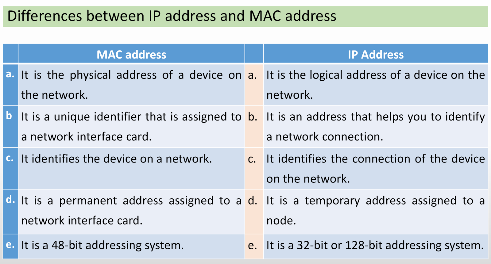
Internet Protocol (IP) Address
• It is a logical address of a node (i.e. a computer or network device)
that identifies the node on the internet or a local area network.
• IP addresses allow nodes to connect and transfer data on the local
area network or the Internet.
• A node on the network can be assigned a static IP address or a
dynamic IP address.
• The static IP address is the permanent IP address that is assigned by a
user itself to a node.
• The dynamic IP address is the IP address that changes each time a
node is reconnected to the network. A dynamic IP address is assigned
by a router to a node whenever the node is connected to the
network
Types of IP Addressing System
• IPv4
• IPv6
IPv4 Addressing System
• It uses 32 binary bits to create a unique identification number for a
node on the network.
• It is expressed as a set of four numbers separated by dots. Each set
can have a decimal number from 0 to 255 and is represented by eight
binary digits, also called an octet.
• IPv4 address is ranged from 0.0.0.0 to 255.255.255.255.
• It allows 232 i.e. 4,29,49,67,296 unique addresses.
The IPv4 addresses range from 0.0.0.0 to 255.255.255.255 are divided into
five ranges.
The five ranges of IP addresses are known as Class A, Class B, Class C, Class D
and Class E.
Each class has a range of valid IP addresses.
The class of IP address is used to determine the bits used for network ID and
host ID.
It also determines the number of networks and hosts possible in the
particular class.
The first three classes A, B, and C are commonly used.
The class D is reserved for multicast and class E is reserved for research
purpose.
This IP address class is used when there are a large number of hosts. In a Class A type of network, the first 8 bits (also called the first octet) identify the network, and the remaining have 24 bits for the host into that network.
An example of a Class A address is 102.168.212.226. Here, “102” helps you identify the network and 168.212.226 identify the host.
Class A addresses 127.0.0.0 to 127.255.255.255 cannot be used and is reserved for loopback and diagnostic functions.
Class B Network
In a B class IP address, the binary addresses start with 10. In this IP address, the class decimal number that can be between 128 to 191. The number 127 is reserved for loopback, which is used for internal testing on the local machine. The first 16 bits (known as two octets) help you identify the network. The other remaining 16 bits indicate the host within the network.
An example of Class B IP address is 168.212.226.204, where *168 212* identifies the network and *226.204* helps you identify the Hut network host.
Class C Network
Class C is a type of IP address that is used for the small network. In this class, three octets are used to indent the network. This IP ranges between 192 to 223.
In this type of network addressing method, the first two bits are set to be 1, and the third bit is set to 0, which makes the first 24 bits of the address them and the remaining bit as the host address. Mostly local area network used Class C IP address to connect with the network.
Example for a Class C IP address:
192.168.178.1
Class D Network
Class D addresses are only used for multicasting applications. Class D is never used for regular networking operations. This class addresses the first three bits set to “1” and their fourth bit set to use for “0”. Class D addresses are 32-bit network addresses. All the values within the range are used to identify multicast groups uniquely.
Therefore, there is no requirement to extract the host address from the IP address, so Class D does not have any subnet mask.
Example for a Class D IP address:
227.21.6.173
Class E Network
Class E IP address is defined by including the starting four network address bits as 1, which allows you two to incorporate addresses from 240.0.0.0 to 255.255.255.255. However, E class is reserved, and its usage is never defined. Therefore, many network implementations discard these addresses as undefined or illegal.
Example for a Class E IP address:
243.164.89.28
Types of IP Address (Private/ Public)
IPv6 Addressing System
• It was developed in 1998 to handle the increased number of Internet users
in the future.
• It uses a 128-bit long addressing system and is expressed by eight sets of
four hexadecimal digits separated by a colon.
• IPv6 addressing system allows 2128 i.e. 3.4028x1038 unique addresses.
Example: 2DAB:FFFF:0000:32EA:01AB:00FD:DD65:2D4B
Subnet Mask
•Each node on a network has an IP address and a subnet mask.
•A subnet mask is a 32 bit number that is divided into four segments separated by dots, just like an IP address.
• It defines the range of IP addresses that can be used within a network or subnet.
• It is used by a computer to determine the location of another computer on the network.
Gateway
• A network node or device that connects local devices or nodes of a LAN to other networks or the Internet is known as a gateway or default gateway.
• It forms a passage between two networks operating with different transmission protocols.
MAC Address
• Media Access Control (MAC) address is the physical address (i.e. hardware
address) of a NIC that connects a node to the network or the Internet.
• It identifies a device on a network and helps for communication between
devices on a LAN.
• It is a 48 bits unique permanent address of a NIC, which is assigned by the
manufacturer.
• AMACaddressof aNIClooks like the given below:
• 00-FF-2B-ED-D0-E6
• 00:FF:2B:ED:D0:E6
Uses of MAC Address
• to connect device physically on the network and identify device on
the network.
• to provide a secure way to find senders or receivers on the network.
• to track the device in case of it gets lost.
• to block an unknown device from connecting to the router. The MAC
filtering feature in the router enables you to prevent unwanted
network access.
• to troubleshoot connection problems on a network.
Internet
• It is the global network of computers interconnected using TCP/IP.
• It is the network of computer networks.
• There are many server computers of different organizations,
companies, universities, offices, public, schools, etc. on the Internet,
which provide a variety of services to a client computer connected to
the Internet.
• There is no central body that controls the Internet.
• It is the largest publicly accessible network and any client (general
public) connected to the Internet can access communication, World
Wide Web(WWW),email, internet relay chat (IRC), remote accessing,
file transferring, video conferencing, etc. services.
Intranet
• An intranet is a private network used by an organization for employees and is
accessible only by employees of that organization and not by other general
people. The networking of computers among the different branches of a bank is
an example of an intranet.
• It helps employees to store, organize and share information, communicate with
each other and collaborate within the organization.
• It is more secure than the Internet.
• The intranet can be cloud-based, hosted on-site, or on off-site servers.
• An organization uses the intranet to:
Share organizational data and files.
Connects employees.
Store files securely.
Connect employees.
Collaborate with teams across borders.
Increase employee productivity.
Give employees a voice in the organization.
Extranet
• It is a web portal that is accessible by an organization and its business
partners, suppliers, customers and other authorized parties that
require access to restricted information.
• It can be shared by more than one organization, such as a business
that allows its vendors to access the company extranet for product
and billing purposes.
• The extranet is used for business-to-business functions like
exchanging large volumes of data between business partners,
monitor issues and deal with any issues relating to a company’s
products and services.
• The ATM network of a bank is an example of an extranet where the
bank provides access to other banks and customers.
Internet Vs Intranet Vs Extranet
NETWORK TOOL: PACKET TRACER, REMOTE LOGIN
• Packet Tracer is a simulation software designed by Cisco
Systems used for practice, design and troubleshooting networks. It helps to
understand the network practically.
• Remote login, also known as remote access, is the ability to access
the data stored on a computer from a remote location. AnyDesk, Teamviewer, PcAnywhere, etc. are some of the more popular remote login tools.
NETWORK CONNECTING DEVICES
Network Interface Card (NIC)
• A network adapter or Network Interface Card (NIC) or LAN card or
Ethernet card is the interface card through which a computer is
connected to the network.
• It is needed to be installed in one of the empty expansion slots on a
motherboard. Nowadays, wireless NICs are becoming more popular.
• The manufacturer of NICs assigns a unique permanent address to a
NIC, which is known as a Media Access Control (MAC) address.
• A user can assign a unique Internet Protocol (IP) address to a NIC
attached to a computer.
Network Switch
NETWORK CONNECTING DEVICES
• A network switch also called multiport network bridge, is a networking device that has multiple connecting
ports through which computers, network devices, and network segments are interconnected.
• It is a full-duplex device and has a separate collision domain for each switch port. Each device connected to a
switch port can transfer data to any of the other ports at any time, and the transmissions will not interfere.
• A switch can determine the source and destination of the data packets or data frames by examining the MAC
address and corresponding port.
2.12 NETWORK CONNECTING DEVICES
• A router is a network layer (i.e. layer 3) internet working device that connects multiple networks
that have the same protocol.
• It is also used to connect computers,laptops,mobile phones,etc.to the Internet.
• A router use sarouting table to maintain network IDs of the networks.
• It works on the basis of IP addresses.When a router receives data packets on its port, it checks
the network address,i.e.IP address of the data packets and determines whether the data packets
need to be forwarded to other network or not with the help of the routing table.
MODEM
• A modem (Modulator Demodulator) is a network device that can convert
digital signals into analog signals and vice versa.
• The conversion of digital signals into analog signals is known as
modulation.
• The conversion of analog signals into digital signals is known as
demodulation.
Network Topology
• The network topology describes how the computers and networking
devices are connected to each other through network cables and how
they communicate.
• The network topology is the cabling pattern of interconnection of
computers on the network.
• There are three basic network topologies. They are
Bus topology, Ring
topology and Star topology.
Bus Topology (Linear Topology)
• In the bus topology, all nodes are connected to a common cable (i.e. network bus or trunk) in a linear
format.
• The network bus is a cable formed by joining many segments of coaxial cables with BNC jacks and T
connectors.
• The network interface card of each computer is connected to the network bus through a T-connector. The
terminators are attached at both ends of the network bus.
• A server can be placed anywhere on the network.
• When any node on the network sends data, the data is broken down into small parts called datagram or data packet and transmitted through the bus in both directions.
Advantages of Bus topology
• It is simple and easy to setup.
• It requires a less amount of cables. So, it is cheap topology.
• It broadcasts the messages to each device connected through the network cable.
• The failure of one workstation does not affect other computers on the network.
Disadvantage of Bus topology
• The entire network does not work if there is a problem in any segment of
network cable.
• It is difficult to find fault in this topology.
• It provides limited flexibility for change. Adding or removing nodes in between is
not easy.
• No node can be added or removed without disturbing the entire network.
• Performance degrades as additional computers are added.
Ring Topology
• In the ring topology, all the nodes are connected in a closed loop or a ring.
• There is no end point in the ring topology.
• Each computer in this topology acts like a repeater that boosts an incoming signal
before passing it on to the next computer.
• In this topology, signals are transmitted in one direction, i.e., clockwise or anti
clockwise.
• Each node amplifies the signals and forwards to another node. When the signals
reach the destination node, it receives the signals.
Advantages of Ring topology
• It is easy to setup.
• Because data travels in one direction, high speeds of transmission of data are
possible.
• Each node on the ring acts as a repeater, allowing ring network to span greater
distances than other physical topologies.
Disadvantage of Ring topology
• The entire network does not work if any segment of cable or node fails.
• It is difficult to find error in the ring topology.
• No node can be added or removed from the network without disturbing the
entire network.
• Since the signals pass through each node in sequence, the addition of new nodes
in the network increases the communication delays.
Star Topology
• It is the most popular network topology used to connect computers and other
network devices.
• In a star topology, nodes are connected to a centrally-located device called a
hub/switch.
• In the star topology, twisted pair cables (especially UTP cables) are used for
joining nodes to a hub or switch.
• Each segment of cable is attached with RJ-45 jacks. One side of the cable is
connected to the node and other side is connected to the hub or switch.
Advantages of Star topology
• A node can be added or removed from the network without disturbing the entire
network.
• If any node fails, it does not affect the remaining portion of the network.
• It is easy to find the fault in this topology.
• It can be easily extended to any size. That means it is suitable for a large network.
• There is less chance of failure of nodes due to cables, connectors and other
networking devices. So, it is one of the most reliable network topologies.
Disadvantage of Star topology
• The failure of the hub/switch affects the entire network.
• Since each node is connected individually to a central hub/switch, more length of
cable is needed.
• It is a little bit expensive as it requires extra cables and other controlling devices.
BASIC CONCEPT OSI REFERENCE MODEL
• The OSI model and the TCP/IP model are the two reference models that describe
data communication between computing systems over a network.
• Open System Interconnection (OSI) model
It was developed by the International Standards Organization (ISO) in 1984.
It is a conceptual framework used to describe the functions of a networking
system.
In the OSI reference model, the communications between computing systems
over a network are described in seven different layers: Physical, Data Link,
Network, Transport, Session, Presentation, and Application.
These seven layers are interconnected separate layers that describe how data
flows from a sender to a receiver over a network.
• TCP/IP model
The TCP/IP model is practically used for communicating between computer
systems over a network.

Application Layer:
Function: Generates data for communication (e.g., sending an email or browsing a website).
Process: Creates messages or requests that need to be sent.
Presentation Layer:
Function: Prepares data for the network.
Process: Translates, encrypts, or compresses data as needed (e.g., converting text into a suitable format).
Session Layer:
Function: Manages communication sessions.
Process: Establishes, maintains, and ends connections between applications (e.g., ensuring a chat session remains active).
Transport Layer:
Function: Ensures reliable data transfer.
Process: Breaks data into packets, adds sequence numbers, and handles error checking (e.g., using TCP).
Network Layer:
Function: Routes packets across networks.
Process: Adds IP addresses to packets and determines the best path for them.
Data Link Layer:
Function: Manages data transfer between nodes on the same network.
Process: Encapsulates packets into frames, adds MAC addresses, and ensures error-free transmission.
Physical Layer:
Function: Transmits data over the network medium.
Process: Converts frames into signals (electrical, optical, or radio) and sends them through the network.
Summary of Data Flow:
Application Layer: Data is generated.
Presentation Layer: Data is formatted, encrypted, or compressed.
Session Layer: Session management and synchronization.
Transport Layer: Data is segmented and transport headers are added.
Network Layer: IP addresses are added, and packets are routed.
Data Link Layer: Frames are created with MAC addresses and error checking.
Physical Layer: Data is converted to signals and transmitted over the network.


Comments
Post a Comment